Hardware Overview
Get Acquainted With The Hardware
There are now many flight controllers on the market tailored for fixed wing. This section provides a high level overview of the typical components and suggestions for wiring both fixed wing and multicopter FCs.
Components
The flight controller is the central processing computer that runs INAV and interfaces with other sensors to make navigation enhanced flight possible. This section outlines the components needed depending on the kind of build.
Bare Necessities
- Flight controller
- Radio control link receiver
INAV can function without any extra sensors and be used as a simple flight stabilization system. This can be useful for certain visual line of sight flying (VLOS).
Navigation Essentials
In addition to everything in Bare Necessities:
- GNSS/GPS
A GPS unit, with or without a compass/magnetometer, is all that's needed to gain full functionality of INAV's navigation features. This will allow for things like return to home (RTH), altitude hold, position, hold, waypoint missions, and more.
FPV (First Person View) Build
In addition to everything in Navigation Essentials:
- Video transmitter (VTX)
- Camera compatible with VTX system
There are now a multitude of video systems for FPV available. These range from the inexpensive, old, but still widely used analog video systems to digital systems such as DJI, Caddx Walksnail, Caddx Ascent, Betafpv P1, and OpenIPC.
It is possible to fly FPV without a GPS, but is not recommended. There will be no OSD aids or safety features like return to home without a GPS.
Sensor Enhanced
In addition to everything in FPV Build:
- Airspeed sensor (pitot)
- Rangefinder
- Buzzer
- Addressable LED strip
- Telemetry Radio
- Second ELRS receiver for Companion Flight
- Companion computer
Connection Inputs and Outputs
The flight controller communicates with peripheral components mentioned above using standardized protocols:
- UART: Universal Asynchronous Receiver/ Transmitter
- I2C: Inter-Integrated Circuit
- SPI: Serial Peripheral Interface
- CAN: Controller Area Network
UARTs are the most common way to add sensors to a FC. It is a one-to-one connection where only one device can talk to one UART resource on the FC. They are denoted as TX and RX in the flight controller manuals and wiring diagrams and must be crossed from device to FC. Peripherals like ELRS receivers, Crossfire receivers, and GPS units communicate with the FC over a UART.
I2C is a two wire serial bus that has one master device (FC) and multiple slave devices (external magnetometer). Pads marked with SCL and SDA on the FC indicate a I2C connection.
SPI is a multi wire, single master (FC) to multiple slave devices where each slave device has a dedicated wire. SPI devices are usually on the FC to interface with on board devices like barometers, multiple IMUs, and SD card access.
CAN is similar to the CANBUS found in modern cars. INAV 10.0 adds DroneCAN (formerly UAVCAN v0) support, using the CAN bus to talk to peripherals such as battery monitors and GNSS receivers.
Fixed Wings
The Flight Controller (FC)
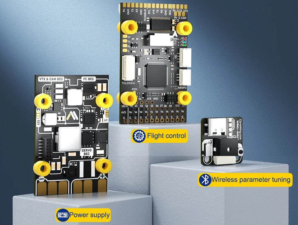
Unlike multicopter flight controllers (FC), fixed wing FCs can come in many different form factors. There are stacked designs that consists of discrete boards connected by header pins or wires and single board designs that are self contained. Often times, the discrete board is the PDB or an accessory module as found on the Corewing F405 V2 board shown below:
Corewing F404 V2 Stacked Design
AtomRC F405 Navi Single Board Design
A popular example of single board FC is the AtomRC F405 Navi as pictured below:
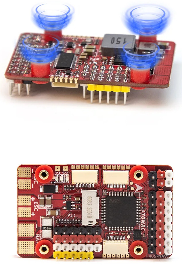
These FCs typically contain all the hardware needed to power and wire up hardware needed for fixed wings. Since fixed wings in the hobby are usually single or twin motors, the electronic speed controllers (ESC) for the motors will have to be sourced separately and soldered onto the specified pads on the FC.
Whether single board or stacked, all will contain a PCB layer that's flat bottomed and intended to be used as a mounting surface.
Flight Controllers are typically equipped with accelerometers. These devices are sensitive to shocks. When the device is not yet installed to an aircraft, it has very little mass by itself. If you drop or bump the controller, a big force will be applied on the internal components of the accelerometer, which could potentially damage them. Bottom line: Handle the board very carefully until it's installed on an aircraft!
Mounting the FC
The FC is best positioned as close to the center of gravity (CG) as possible. There is no one correct way of mounting the FC into the aircraft.
With Adhesive
For smaller builds as found on the AtomRC Dolphin, Swordfish, and Beluga, the FC comes from the factory secured on a plywood tray with strong double sided tape. This has been the easy, de-facto method for mounting the FC in a fuselage as shown by many people on Youtube such as Painless360.
Alternatively, hot glue can also be used for a quick and secure method.
With Screws
For those who wish to take it a step further, the mounting holes on the FC can be used to secure it to a secondary mounting plate that is then secured to the fuselage either through adhesive means or through another set of mounting screws. Many of the fixed wing FC utilize M2 screws and a non-standard mounting pattern. The most common pattern has been found to be the same as that of multirotor FCs: 30.5mm square. There are several examples of these designs found on Thingiverse and Printables.
Wiring Guide
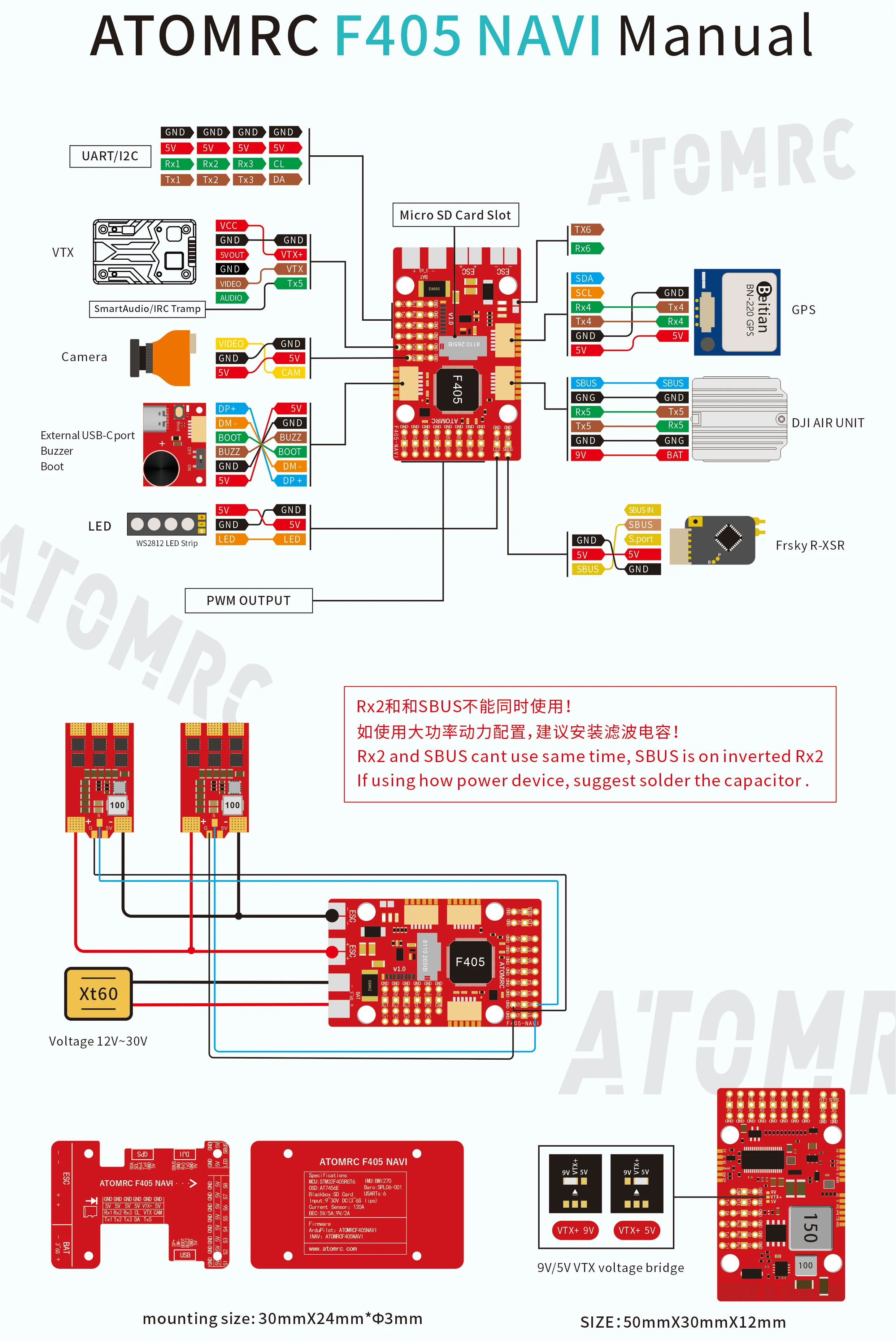
Most FC on the market will come with a wiring guide in the manual or found online on the manufacturer's website. These guides illustrate which ports are the recommended ports for all the peripherals eg. (GPS, RX, Camera, VTX, Servos). It is generally advisable to follow the manufacturer's manual unless otherwise specified as there might be jumper pads that can be bridged to do things such as change servo output voltage from 5V to 9V and bypass the BEC for direct battery power to the VTX.
The usual components that are found on a FPV build are:
- Receiver (ELRS, TBS Crossfire, Frsky, etc)
- GPS
- Servos
- VTX/Camera (either digital or analog)
- Buzzer (can be found built into the FC's USB board)
UART components will need their TX and RX wires crossed (TX from GPS goes to RX on FC). Most manuals will show this in their wiring guides.
As an illustrated example, the wiring guide for the AtomRC F405 Navi is shown below:
Power Wires
Powers wires from the battery and to the ESC(s), should be a thicker gauge wire. Depending on the size of the aircraft, a good starting point for average, parkflier sized aircraft is 16awg to 14awg.
It's also a good idea to mount a capacitor on the battery pad. The capacitor is provided in FC packaging along with the wiring accessories for all the peripherals. There are two ways to mount the capacitor: directly on with the legs or slightly discreetly using wire extensions.
For larger builds that have bigger motors and more current flow, 12awg is a good idea. Keep in mind the servos' current draw is within limits of the FC's servo BEC, otherwise the servos will have to be powered with an external voltage regulator.
Multicopters
Flight Controller (FC)
Multicopter FCs are fairly standardized and come in three distinct form factors:
- 30.5mm stack
- 20mm stack
- 25mm AIO stack
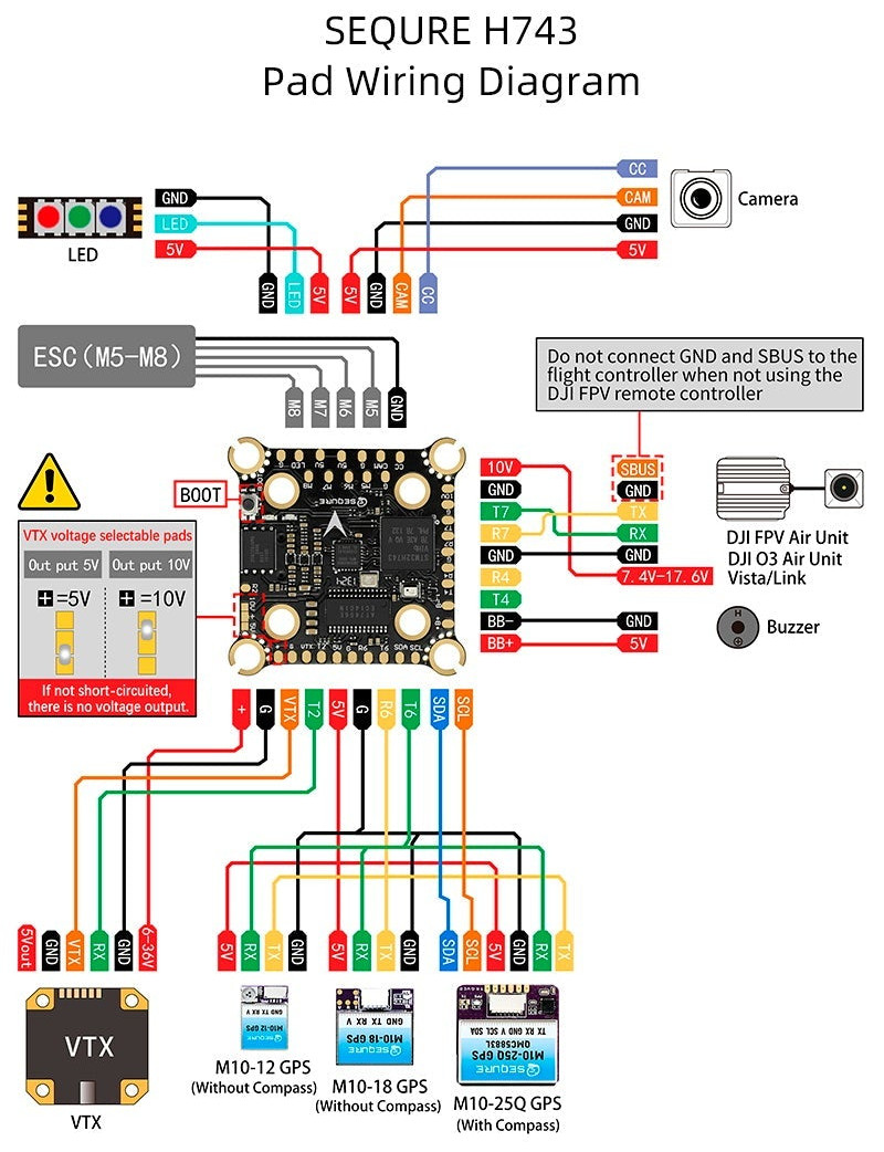
Each of these stacks are wired in the same paradigm as fixed wing FCs. The only difference is that they are sized and optimized for multicopter form factors. This includes having a (usually) 8 pin JST 1.0 cable that connects the FC to the ESC. An example of how a typical MC FC is wired is shown below: