OSD HUD and Craft Radar
The HUD draws points of interest (POI) onto the OSD as markers, placed where the object appears in the camera image. The position of each marker is calculated from the attitude and heading of the aircraft, the position of the POI, and the field of view of the FPV camera. Three kinds of POI can be drawn:
- The home point.
- Other aircraft, called peers, whose positions are supplied by an external radio module.
- The next waypoints of a mission.
This page covers the HUD and the craft radar only. General OSD setup, the full element list, the character grids of the various video systems, and fonts are described in OSD. Two related pages are also useful: Custom OSD Elements, and the In-Flight OSD Menu, which lets you change these settings while airborne.
The crosshair is the origin of the HUD
The HUD markers are drawn as part of the crosshair element, which acts as their reference point.
The Crosshair element must be enabled in the Configurator OSD tab, or no HUD marker will appear at all. With the crosshair disabled there is no HUD, and the home, peer and waypoint markers are not drawn.
The fixed-position peer display described under Showing other aircraft is a separate OSD element and does not need the crosshair.
Avoid putting the legacy map elements in the same layout as the HUD. Both draw across a large part of the screen, so they will overlap each other.
Camera geometry
To place a marker correctly the HUD needs to know how the FPV camera sees the world. These settings are in the Configurator OSD tab, in the CLI, and in the OSD menu under OSD > HUD.
| Setting | Default | Range | Notes |
|---|---|---|---|
osd_camera_uptilt | 0 | -40 to 80 | Angle in degrees between the horizontal of the aircraft and the line of sight of the camera. Positive is up, negative is down. |
osd_camera_fov_h | 135 | 60 to 150 | Horizontal field of view of the camera, in degrees. |
osd_camera_fov_v | 85 | 30 to 120 | Vertical field of view of the camera, in degrees. |
osd_hud_margin_h | 3 | 0 to 4 | Left and right margins of the HUD area, in characters. |
osd_hud_margin_v | 3 | 1 to 3 | Top and bottom margins of the HUD area, in characters. |
osd_horizon_offset | 0 | -2 to 2 | Shifts the whole OSD, the artificial horizon and the scrolling sidebars vertically. |
osd_ahi_camera_uptilt_comp | OFF | ON, OFF | When ON, the artificial horizon position is compensated by osd_camera_uptilt. |
A multirotor usually has the camera tilted up, so osd_camera_uptilt is a positive value, often between 5 and 30.
A plane with a slightly downward-looking camera needs a negative value, often between -5 and -10.
:::warning Do not use the HUD to show other aircraft on a multirotor A multirotor can hover on the spot and rotate on its yaw axis. The HUD then places peers in the wrong direction, because it draws them relative to where the camera is pointing. On a multirotor, show peers with the fixed element instead - see Showing other aircraft below. The rest of the HUD, such as the home point marker, is unaffected. :::
The default field of view values suit a 2.8 mm lens. A shorter focal length sees more, so with a 2.5 mm or 2.1 mm lens raise both values in steps of 5 or 10 degrees. If the field of view is badly wrong, markers will drift away from their true position towards the edges of the screen.
The margins keep the HUD clear of the rest of your OSD layout. Markers are confined to the resulting area, so a POI that is inside the camera view but outside that area is shown as an edge marker instead.
Leave osd_horizon_offset at 0 unless you have a specific reason to change it.
Crosshair style
Eight crosshair styles are available through osd_crosshairs_style: DEFAULT, AIRCRAFT, TYPE3, TYPE4, TYPE5, TYPE6, TYPE7 and TYPE8.
The shapes come from the OSD font, so they only look correct with a current font uploaded.
Displayed items
These settings select what the HUD actually draws.
| Setting | Default | Range | Notes |
|---|---|---|---|
osd_hud_homing | OFF | ON, OFF | Small arrows around the crosshair pointing towards the home point. |
osd_hud_homepoint | OFF | ON, OFF | Draws the home point as a 3D marker. |
osd_hud_radar_disp | 0 | 0 to 4 | Maximum number of peers or POIs to display. 0 disables the peer display entirely. |
osd_hud_radar_range_min | 3 | 1 to 30 | Peers closer than this, in metres, are not drawn. |
osd_hud_radar_range_max | 4000 | 100 to 9990 | Peers further away than this, in metres, are not drawn. |
osd_hud_radar_alt_difference_display_time | 3 | 0 to 10 | Seconds for which the altitude difference is shown below a marker. |
osd_hud_radar_distance_display_time | 3 | 1 to 10 | Seconds for which the distance is shown below a marker. |
osd_hud_wp_disp | 0 | 0 to 3 | How many upcoming waypoints to draw. 0 disables them. |
osd_hud_radar_disp defaults to 0, so the peer display is off until you raise it.
The two range limits are always in metres, whatever unit system the rest of the OSD uses.
The minimum range mostly exists to keep the OSD uncluttered during close-range pursuits.
The waypoint markers are numbered relative to your progress through the mission, not by their absolute mission index.
With osd_hud_wp_disp set to 2, having just passed the third waypoint, the fourth and fifth waypoints are drawn as 1 and 2.
The area below a peer or waypoint marker alternates between the altitude difference and the distance. The two display time settings above control how long each of them is shown.
What a marker looks like
The home point is drawn with the home symbol from the OSD font, which is usually a small house or the letter H. Below it is the distance, in metres or kilometres when the OSD is set to metric or UK units, and in feet or miles when it is set to imperial.
Peers are drawn as the letters A, B, C and so on, according to the slot the module reported them in. Waypoints are drawn as a number with an icon beside it.
A peer marker carries more information than the other two.
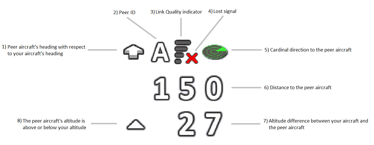
| Item | Meaning |
|---|---|
| 1 | Heading of the peer relative to your own heading, in eight steps of 45 degrees. An arrow pointing up means you are both flying the same way, and pointing down means you are flying towards or away from each other. |
| 2 | The peer ID letter. |
| 3 | Link quality, reported by the module on a scale of 0 to 4. |
| 4 | Shown in place of the link quality bars when the module reports the link as lost. |
| 5 | Cardinal direction to the peer, as a twelve point pointer. |
| 6 | Distance to the peer. |
| 7 | Altitude difference between your aircraft and the peer. |
| 8 | Whether the peer is above or below you. |
The heading arrow and the cardinal pointer answer different questions, and both are needed. The cardinal pointer tells you where the peer is, for example at two o'clock. The heading arrow tells you which way it is travelling, so you can tell whether it is closing on you, moving away, or crossing your path. Using the two together lets you set a course that intercepts the other aircraft rather than chasing it.
Peer markers always keep their cardinal pointer, even when the peer is behind you and well outside the camera view. Markers for POIs that are out of sight are stacked vertically near the edge of the HUD area so that they do not overwrite each other.
The layout is the same on analogue and digital systems. Digital systems can show it in colour, but they need a video system with full support for the INAV font set.
Showing other aircraft
There are two independent ways to show peers, and you can use either or both.
The first is the HUD described above, which places a lettered marker where the peer is in the image.
It requires the crosshair, and is controlled by osd_hud_radar_disp.
The second is a fixed-position element that always draws in the same place on the screen.
It shows one peer at a time and cycles through the available peers, spending osd_radar_peers_display_time seconds on each.
| Setting | Default | Range | Notes |
|---|---|---|---|
osd_radar_peers_display_time | 3 | 1 to 10 | Seconds each peer is shown before the display moves on to the next one. |
:::warning Pick the right element The OSD element that shows peers is OSD_FORMATION_FLIGHT, which the Configurator lists under Maps & Radar. The element named OSD_RADAR is not the peer display at all. It draws a map of your home point relative to your aircraft, and it shows no other aircraft. :::
The name refers to the OSD element, not to the hardware or the protocol. It displays whatever peers reach the flight controller, whether they come from a Formation Flight module or from the older ESP32 radar firmware.
The fixed element needs a GPS fix and a valid heading, but it does not need the crosshair. That is why it is the right choice on a multirotor, and it works on a plane just as well.
How peer data reaches the flight controller
Peer positions are not sensed by the flight controller. They are pushed into it over MSP by an external module, which owns the radio link between the aircraft.
| Message | ID | Direction | Purpose |
|---|---|---|---|
MSP2_COMMON_SET_RADAR_POS | 0x100B | Module to flight controller | Sets the position and state of one peer slot. |
MSP2_COMMON_SET_RADAR_ITD | 0x100C | Module to flight controller | Sends radar information to display. |
MSP2_COMMON_GET_RADAR_GPS | 0x100F | Flight controller to module | Returns the stored position of every peer slot. |
MSP2_COMMON_SET_RADAR_POS carries one peer update, in this order.
| Field | Size | Units |
|---|---|---|
| Slot | 1 byte | Peer slot number, clamped to the number of available slots. |
| State | 1 byte | 0 is undefined, 1 is armed, 2 is lost. |
| Latitude | 4 bytes | Degrees, multiplied by 1e7. |
| Longitude | 4 bytes | Degrees, multiplied by 1e7. |
| Altitude | 4 bytes | Centimetres. |
| Heading | 2 bytes | Degrees. |
| Speed | 2 bytes | Centimetres per second. |
| Link quality | 1 byte | 0 to 4. |
The firmware keeps five peer slots.
A slot is drawn only while it holds a non-zero position and its state is not "lost", and the number drawn on the HUD is additionally limited by osd_hud_radar_disp.
Distance, bearing and altitude difference are all computed on the flight controller from the reported position, so only position, heading, speed and link quality travel over the link.
The firmware applies no timeout to peer positions. A peer marker stays on screen at its last reported position until the module updates it or reports that slot as lost. If the radio link drops silently, the marker keeps showing stale information instead of disappearing, so do not rely on it for separation.
Radar hardware and firmware
The module is third-party hardware running third-party firmware, and INAV only consumes the MSP messages above. Two projects are in common use, and INAV works with either.
- The ESP32 LoRa modem project, usually called INAV Radar. See the discussion at RCGroups for hardware and firmware details.
- FormationFlight, a separate project that runs on hardware of the kind used by ExpressLRS. Support is available on its Discord server.
Consult the documentation of whichever project you choose for its own wiring, configuration and capabilities.
Connecting the module
Wire the module to a spare UART on the flight controller, exactly as you would a GPS, using 5 V, GND, TX and RX.
A softserial port is not fast enough for this and is not supported. Use a hardware UART.
In the Configurator Ports tab, enable MSP on that UART and set the speed to 115200. Nothing else needs to be configured on the port, because the module talks to the flight controller with standard MSP messages.
On a plane, raise osd_hud_radar_disp above 0 to display peers on the HUD, and add the OSD_FORMATION_FLIGHT element if you want the fixed display as well.
On a multirotor, leave osd_hud_radar_disp at 0 and use the OSD_FORMATION_FLIGHT element on its own.
Example settings
These CLI values enable the HUD with both the home point and peers displayed.
set osd_crosshairs_style = DEFAULT
set osd_horizon_offset = 0
set osd_camera_uptilt = 0
set osd_camera_fov_h = 135
set osd_camera_fov_v = 85
set osd_hud_margin_h = 3
set osd_hud_margin_v = 3
set osd_hud_homing = ON
set osd_hud_homepoint = ON
set osd_hud_radar_disp = 4
set osd_hud_radar_range_min = 3
set osd_hud_radar_range_max = 4000
set osd_hud_wp_disp = 2
save
Adjust osd_camera_uptilt, osd_camera_fov_h and osd_camera_fov_v to match your own camera and its mounting.
Accuracy and limitations
Several sources of error add up, so marker placement is approximate rather than exact.
- The heading of your aircraft can be significantly wrong during a hard turn, or immediately after one. The steadier the flight, the better the tracking.
- Marker placement depends on the attitude and heading of your own aircraft, so an error of a few degrees moves the markers noticeably.
- The projection deliberately ignores the roll angle of the aircraft to stay simple and fast, so it degrades at high bank angles.
- Character based OSDs can only place a marker on a whole character cell, which sets a floor on precision. The grids of the different video systems are listed under Features and Limitations.
- On analogue systems the crosshair cannot be perfectly centred, because the character grid has an even number of columns and rows.
- Peer positions are only as fresh as the last update from the module, so at speed the relative geometry lags reality.
Troubleshooting
The module reports that it cannot see the flight controller.
Check all four wires, and confirm that the UART has MSP enabled at 115200 baud in the Ports tab. A softserial port will not work.
No markers appear at all.
The HUD needs the crosshair element enabled, a valid GPS fix, and a known heading. Without a magnetometer the heading is only known once you are moving, so you have to reach forward flight with a good fix before any marker appears. This applies to planes, multirotors, rovers and boats alike.
The home marker additionally requires the home point to be set, which happens on arming. Peer markers do not need a home point.
Peers never appear, but the module reports a good link.
Confirm that osd_hud_radar_disp is not 0, and check that the peers are between osd_hud_radar_range_min and osd_hud_radar_range_max away from you.
If you added the fixed element instead, make sure it is OSD_FORMATION_FLIGHT and not OSD_RADAR.
Characters are missing or wrong in the HUD.
Upload a current OSD font from the Configurator OSD tab, as described in OSD.