Fixed Wing Setup Guide
This page explains where to connect servos and motors to the FC and how to configure INAV through INAV Configurator to get a working airplane ready for its maiden flight.
Since this is a quickstart guide, advanced configuration for FPV setups is not covered. This is meant to provide a barebones setup to get an aircraft ready for a line of sight flight.
The main parts of this page are:
Prerequsites
- Have INAV Configurator installed and working.
- Flash the FC with its firmware through INAV Configurator
Hooking Everything Up
As an example for this section, we will use the Matek F405 Wing V2, whose picture is shown below.
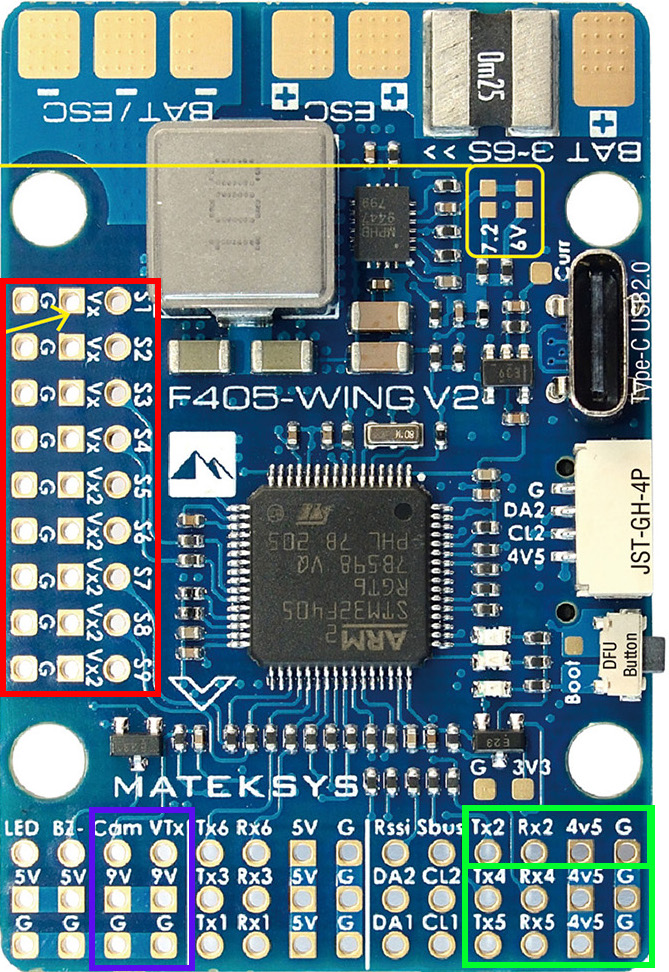
Motor and servo wires are generally connected to dedicated pins on the FC. In the Matek FC pictured above, the pins for motors and servos is boxed in red. These are labeled as S1 - S9 on this FC and are referred to as PWM headers. Other FCs may have more or fewer pins.
Timer Groups
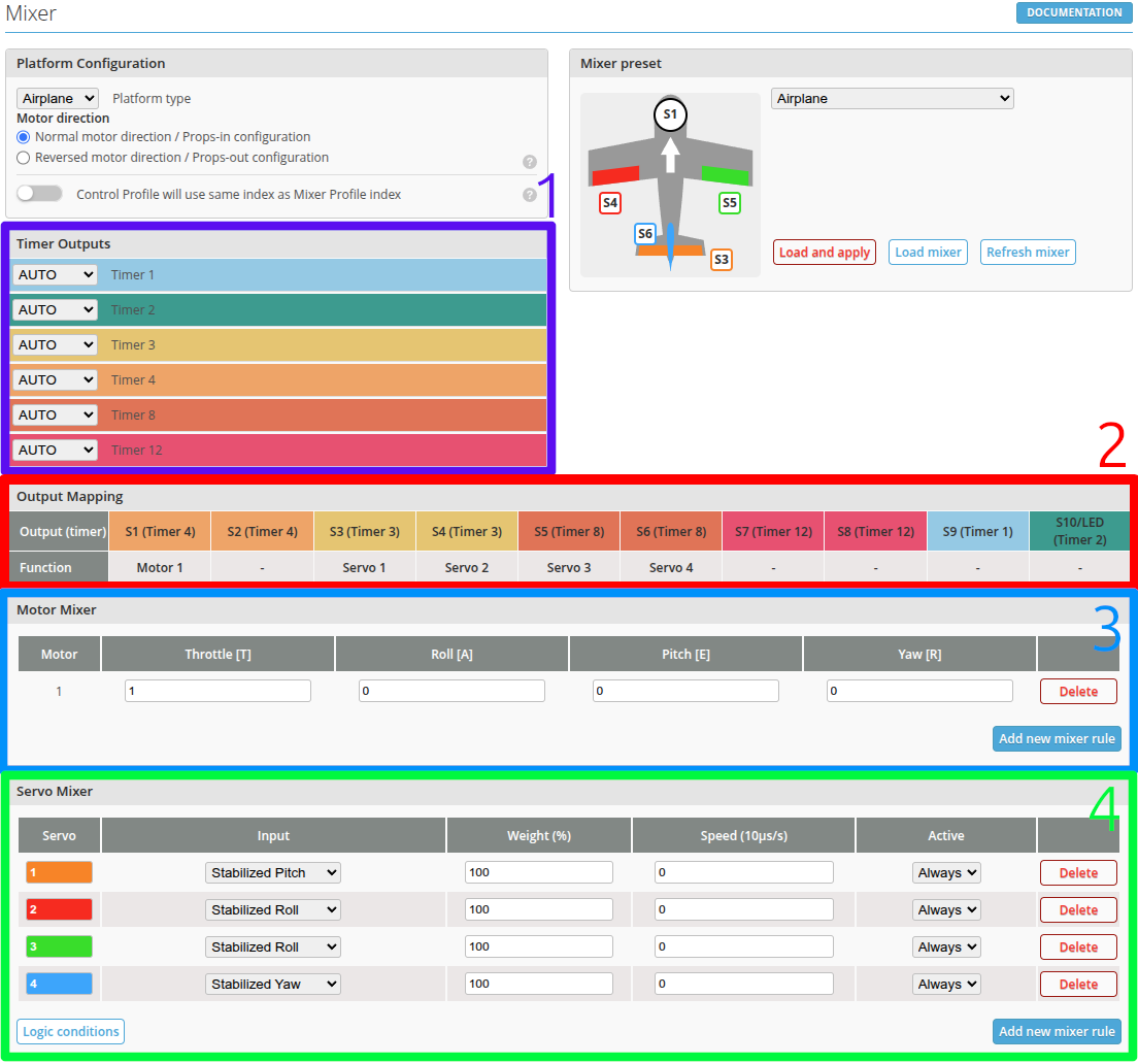
An important concept with STM32 based MCUs that is present in almost all modern FCs on the market is that of timers. Timers are associated with a physical hardware pins on the MCU. A set of pins belong to a certain timer depending on the configuration. These groups of pins that belong to a certain timer are known as timer groups. INAV utilizes these pins in timer groups to allow for flexibility in driving a combination of motors that are DSHOT driven and servos that are PWM driven. The mixer tab in INAV Configurator where this setting is configured is shown below with an explanation of each boxed section under the picture.
-
Timer Outputs - shows the available timers and their functions. By default, all timers are set as
AUTO. To manually set the fuction, click the dropdown. The available functions are: MOTOR, SERVO, and LED. -
Output Mapping - is a table that shows which timers in Box 1 are mapped to which motor and/or servos.
-
Motor Mixer - is where motor outputs are added and configured. To add a motor, press Add new mixer rule and a new motor index will automatically populate the table.
-
Servo Mixer - is wher servo outputs are mapped to their respective pins. Just like a motor, press Add new mixer rule and a new servo index will automatically populate the table.
When the Timer Outputs are set in AUTO mode, the default, predefined timers and their functions will be used. This can be limiting for more complex setups.
Thus it's good practice to first decide which pins/timer groups on the FC you wish to use for motors or servos and define them in the Timer Outputs (Box 1) shown above. Then save and reboot to make those changes active. Then populate the motor and servo mixes by adding them in Box 3 and Box 4.
Example: The Mixer page from the Matek F405 V2 pictured above by default only has motors mapped to Timer 4. This will prevent adding additional motors in a multi engine airplane build. Therefore, it will be necessary to explicitly define the other timers/pins with the MOTOR function instead of AUTO.
Motor Wire(s)
For ESCs with an integrated BEC, do not connect the red wire bringing power from the BEC to the FC. This will potentially ruin the FC!
The motor signal connector(s) simply plug into the signal output pin that has been decided to function as the motor output. Take caution as the timer group that now assigns the chosen group of pins can now only function as MOTOR outputs.
Servo Wires
Servo wires are connected to the signal output pins using the same logic as the motor wires. Be sure to assign the timer group that corresponds to the chosen pins as SERVO. Take note of which servo has been plugged into which pin. This information is necessary for the next step that is configuring INAV's mixer for the kind of airplane being set up.
Peripherals
For the rest of the peripherals such as receivers, GPS, analog or digital cameras, VTX, rangefinders, airspeed sensors, etc, follow the diagram for the FC being used. Generally, UART devices are connected to pins or pads labeled as TX2 and RX2. I2C devices such as the compass on a GPS are connected to SDC and SDA pads. Digital video systems are connected to a UART, typically one that is paired with a power supply that is higher voltage (9v or switchable to higher voltage).
INAV Configuration
After the airplane is physically wired up, the next step is to configure everything in software using INAV Configurator. At this stage, the FC should have had its accelerometer calibrated as descibed in the earlier Acceleromter Calibration Page. The proceeding subsections will outline how to configure the rest of INAV to have a working airplane. Each subsection is titled based off the respective tab in INAV Configurator and should be followed sequentially.
Mixer
In the Timer Groups section, the Mixer page of INAV Configurator was shown. The Timer Outputs should be correctly assigned and defined according to where the motor and servo wires were connected. The next step is to set the Platform type to Airplane and select a mixer preset for the kind of airplane. Then press the Load and Apply button. The motor and servo mixer rules will automatically populate upon the FC rebooting.
In the example above, a conventional airplane is selected. One motor output and four servo outputs are defined and populated.
Motor Mixer
| Motor | Throttle [T] | Roll [A] | Pitch [E] | Yaw [R] |
|---|---|---|---|---|
| 1 | 1 | 0 | 0 | 0 |
The Motor Mixer table assigns defined motors in numerical order. The output pin that it is assigned to is viewed in the Output Mapping table above the Motor Mixer section. The Throttle column is the only one that must have a value of 1 as that is the only control the motor needs. The motor number cannot be reassigned if there are additional motors.
Servo Mixer
| Servo | Input | Weight (%) | Speed (10μs/s) | Active |
|---|---|---|---|---|
| 1 | Stabilized Pitch | 100 | 0 | Always |
| 2 | Stabilized Yaw | 100 | 0 | Always |
| ... | Stabilized Roll | ... | ... | ... |
| ... | Stabilized Roll | ... | ... | ... |
| ... | ... | ... | ... | ... |
The Servo Mixer table assigns servos to their functions. There are three main servo functions in the Input column:
- Stabilized Pitch
- Stabilized Roll
- Stabilized Yaw
If the mixer preset is incorrect, relabel the servo number that corresponds to the pin it belongs to in Output Mapping. Then define the servo function in the Input column. Lastly, save and reboot to apply your settings.
Receiver
Before continuing any further, now is a good time to configure the receiver to ensure INAV is able to read the commands given from your radio.
-
Assuming that a CRSF based serial receiver was used during the FC wiring steps and that the wiring diagram was followed for the respective FC used, assign the UART that the receiver is connected to as RX in the Ports tab in INAV Configurator. Save and reboot.
-
Then head to the Reciever tab and select receiver type as Serial.
After rebooting, the Receiver tab will show the working channels that it is receiving from the radio.
Modes
To make ground setup and configuration easy, the correct flight modes should be setup at this point. For the purpose of setup, enable the following modes on a switch of your choice:
- Manual
- Angle
At this stage the control surfaces can be mechanically centered. Please ensure the airplane has its props removed and is in Manual mode.
With the airplane powered on by a battery, mechanically center the control surface linkages. While in the modes tab, confirm that the correct mode is highlighted by changing the mode switch to their respective positions.
Outputs
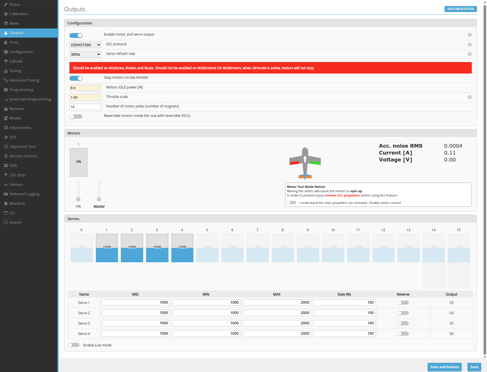
The Outputs tab shows all the configured channels and the PWM output values INAV sends. In this tab, the motors can be tested and/or calibrated if using a PWM ESC. The motor numbering corresponds to the number defined in the Mixer tab.
Use this tab to reverse the direction of a servo so that all control surfaces and servo actuated mechanisms operate as expected.
Servos begin from number 1 and correspond to the servo numbers defined in the Mixer tab.
It is safe to ignore the zeroth servo that appears in the servo section.
It is also possible to reverse servo direction in the Mixer tab by changing the weight to a negative value.
PWM ESC Calibration
ESCs that do not run BLHeli-S, AM32, Bluejay, or BLHeli32 need to be calibrated before first use. Calibration can be performed in a few easy steps:
- Connect FC to INAV and navigate to the Outputs tab. Power the FC on only through USB at first!
- Enable motor and servo output, reboot, and enable the Motor Test Mode in the Motors section.
- Raise the master motor control slider to the max.
- Plug in battery to power the ESC. The ESC will make its usual beeps after a couple seconds.
- Lower the master throttle slider to finish the calibration process.