Compass
Accurately setting up the compass is vital because it is the primary source of heading information.
Without an accurate heading the drone will not move in the correct direction in autopilot modes (POSHOLD, RTH, Waypoint). This can lead to circling (aka “toilet-bowling”) or even fly-aways.
The magnetometer (basically a compass) measures magnetic field strength so it should be placed away from any sources of magnetic interference - power wires, ESCs, motors, beepers, metal parts of the frame, video transmitters, Llamas & so on...
The best way is to place the compass on a mast along with GPS module (if discrete) and away from magnetic sources. When an external compass is used remember to set correct "align_mag", see the INAV CLI variables for more information. The compass must be mounted parallel to FC.
When using an external magnetometer, 9/10 times you need to physically remove (remove chip from board or cut a trace) the internal one if you have on.
Two identical chips/magnetometers on the same I2C bus cannot be used. The 1/10 time you dont need to physically remove your internal mag is when you have different magnetometers on the flight controller and the external one. Example you cannot use two HMC5883L magnetometers.
Setting Up a Compass
INAV's default Orientation Preset is CW270FLIP.
This value is based on the orientation of the magnetometer chip on its PCB, chosen by the manufacturer.
With respect to the arrow direction they provide facing the front of the aircraft or the plug facing the rear of the aircraft.
Compass I2C Speed
In the Configuration Tab, i2C_speed can be altered to keep up with the magnetometers maximum data update rate on higher performance quads.
The default is 400KHz.
This speed works well for all tested magnetometer chips; however the QMC5883 can run an i2C_speed = 800KHz if required.
Other magnetometer chips such as the IST8310 cannot function correctly beyond 400KHz due to its slightly lower maximum data output rate.
Compass Setup Using Presets
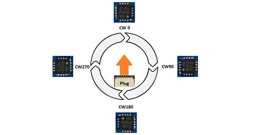
INAV has a library of compass presets in the Alignment Tool Tab that can aid in its configuration. Presets refer to the orientation of the white dot on the magnetometer chip performed in 90 degree clockwise increments and a FLIP suffix to denote when it is flipped 180 degrees upside down about the compass chip's y axis.
When using presets, follow the manufacturer's arrow and select the model of compass/GPS unit being used in the drop down menu.
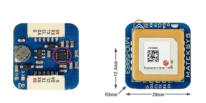
As an example, the Matek M10Q is pictured below:
-
In the left image circled in Red at the base of the GNSS unit is the QMC5883 magnetometer chip with its white DOT providing an axis magnetic bearing reference based on the internal coils.
-
In the right image circled in Orange is the orientation arrow showing the direction the compass should ideally be mounted. That arrow should face the front of the model and its direction of travel along with the flight controllers arrow facing forward as well (unless modified).
Preset Nomenclature
When using presets, the compass's orientation is locked relative to the FC! This means that even when not placing the FC in the manufacturer's default orientation (eg upsidedown or rotated 90 degrees) and modifying that in the Alignment Tab, the compass will follow that orientation change. This will likely have unintended consequences so double check the compass orientation!
Pictured below is the position of the four main presets and the location of the white dot on the chip.
The FLIP Suffix Explained
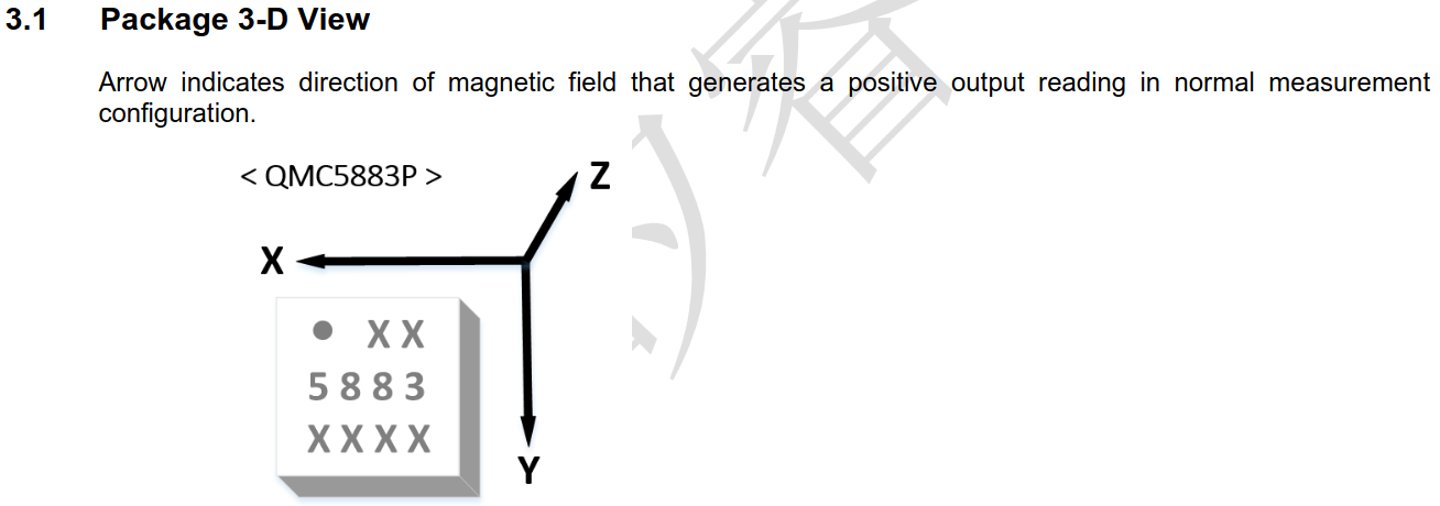
The FLIP suffix denotes that the compass chip is positioned facing down towards the ground by rotating about its y axis. The axes can be found in the compass chip's datasheet.
Enhanced Explanation in #6232 How to Align and Check if your readings are Correct
Painless360 has done a video on this:
Compass and Flight Controller Alignment is Coupled
When using presets, the compass's orientation is coupled with that of the FC's. If you invert the flight controller or rotate it on the Yaw axis, it will mirror the FC's alignment changes. Before attempting to use any navigation modes, verify that the compass alignment is working in unity with the flight controllers alignment. By using the Configurator SETUP/STATUS Tab, and moving the model on all axis's with your hand, ensure the graphical model moves identically to your motions, without any axis drift. Please be mindful of the complexity involved in getting the correct orientation settings if you do decide to mount the flight controller or GNSS/compass unit on an axis different from the manufacturer recommendation arrow.
Example:
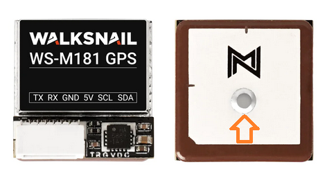
The image below is an example of a module that does not use the default orientation preset, nor has a mounting direction arrow from factory. The orange orientation arrow has been added to the image below to assist your installation if you have this unit. Its Orientation preset is CW180FLIP with the plug facing to the rear of the model. Beitian made the first GPS modules that included a compass for hobby use, back in 2014. And this is how we ended up the confusing default orientation preset of CW270 (flip)
Manual Compass Orientation and Placement
Manual alignment of the compass will be necessary in more complex setups.
When to manually align compass:
- The compass does not have any clear arrow indications
- There is no preset available in INAV for the compass being used
- The FC is mounted in an unconventional position and orientation (eg. upsidedown, cockeyed X degrees, etc.)
- Compass is mounted at an angle
Steps For Manual Compass Setup
First, consult the datasheet of the compass being used. Identify the XYZ axes of the compass chip. The Z axes will typically be normal to the chip (coming out perpendicularly)
- Open the Alignment Tool Tab
- In the second dropdown, select XYZ (Magnetometer Axes) as the element to show in the 3D model.
- Use the compass's X, Y, and Z sliders so that they match the physical orientation the compass is mounted on the aircraft.
- Ensure the angles are then squared away and orthogonal to the aircraft's axes.
The Z axis is normal to the compass chip. When manually configuring the X, Y, and/or Z axes orientation, the preset will be crossed out. The compass will not move its orientation with changes in the FC's orientation and is essentially "decoupled."
Empirical Method for Determining Compass Alignment
Rather than using the alignment tool, it is sometimes easier to instead test the actual readings you are getting from your compass to find its proper alignment. The following procedure can be used:
If the compass is tilted at an odd angle, use a piece of tape or similar to temporarily hold it flat.
-
First ensure the FC alignment is correct. In the Setup Tab it must move the correct direction in all three axis.
-
Then, move the aircraft away from computer monitors and speakers - as far as your USB cable will allow to reduce magnetic interference.
-
Point the aircraft north. Look at the heading in the Setup tab
-
Quickly turn the aircraft 90° so it points east and set it down. Watch the heading reading over the next five seconds. Does it remain stable, or does it slowly change, by more than 10°?
- If the heading slowly catches up over a few seconds, the compass alignment is upside-down.
- If it remains stable, it's right-side up.
- If needed, add/subtract 180° to the roll to flip it.
-
Now that it's right-side up, we need to set which way is front by adjusting the yaw. Adjust the yaw in 90° increments so that the heading reads about 0°/360° when the aircraft is pointed north.
-
Confirm east, south, and west also read correctly. Save and reboot.
-
If you 3D-printed a mount to put the magnetometer at a weird angle, adjust for that now in the alignment tool.
- If you have a tiny whoop board with the 45° angle mounting, you may need to adjust yaw in 45° increments.
That's it, you're done!
Compass Calibration and Testing
Compass calibration is primarily performed in the Calibration Tab The general rule behind compass calibration is to ensure the magnetometer reports the earths magnetic field strength equally on all axis's, regardless of weak localized magnetic perturbations. Therefore calibration of the compass should be done in the aircraft.
Ideally, its not good enough to rotate the compass or aircraft so that each axis faces skyward or towards the ground because this can leave areas where a complete calibration is missed, which will provide poor results and navigation performance.
To acquire the best 3 axis calibration results, your arm and wrist should move the aircraft in a figure 8 or infinity symbol motion in the air, while ensuring every axis faces skywards in the process. Do this several times (not too quickly) within the allotted 30secs.
Use a long USB extension lead if its done via connection to the configurator.
The end result should be the maggain_x maggain_y maggain_z calibrated settings should not be greater that 100 points of each other, and as close to 1500 or 500 as possible, depending on the magnetometer chip used.
While magzero_x magzero_y magzero_z can vary, they should never exceed +- 1000 on any axis of each other.
Any dramatic difference indicates a poor calibration or too much localized magnetic or electromagnetic interference.
A good calibration may take several attempts. So use the above information as a reference if you attempt to obtain a more precise calibration.
Compass Calibration Using INAV Configurator
Calibrate with flight battery powering up the aircraft.
-
Navigate to the Calibration tab in INAV Configurator.
-
Press "Calibrate Magnetometer" button.
-
Within 30 seconds, hold the aircraft in the air and rotate it so that each side (front, back, left, right, top and bottom) points down towards the earth. The algorithm is smart enough to calculate the proper calibration values even if each side does not see a complete rotation after pressing the "Calibrate Magnetometer" button.
Compass Calibration Using Stick Commands
Calibrating Mag/Compass without the need to be connected to a computer can extremely convenient while out in the field. The Stick Controls page describes the various capabilities of adjusting the craft's controls using the TX sticks.
Stick Calibration Steps (Mode 2):
-
Ensure aicraft is disarmed!
-
Move the left stick up and to the right while at the same time, move the right stick down and to the center. The flight controller will sound two quick beeps indicating the start of the calibration.

-
Move the craft as indicated in the paragraph above. After 30 seconds, the flight controller will sound a single beep indicating the completion of the process.
Calibration Tips
- Perform any tests away of sources of magnetic interference. Domestic appliances or even audio speakers can cause erroneous affects. Computer monitors may also interfere.
- Use an analogue compass in preference to a digital (mobile phone) compass. The compass in your phone is likely to be a similar chip to that on your aircraft and is as susceptible to the same errors of interference and calibration
- Alternatively, if you know the orientation of surrounding landmarks (a house, building, street), then you can do static tests against land orientation.
Check your machine at cardinal points (North (0°), East (90°), South (180°), West (270°)). Degree perfect alignment is not necessary (and probably not measurable), but you should aim for +/- 5° of known magnetic direction.
-
If the values are incorrect by a multiple of 90°, then the numeric alignment needs to be changed
-
If the values are just randomly wrong across the cardinal points, then the FLIP alignment setting is probably wrong (as well).
-
If external Compass module is mounted at 30 degree, for example at top of a Cam mount, alignment is possible by Cli commands. Cli setting Align_mag must be set to
Align_mag = defaultsave
For example CW270FLIP, this value is to ADD manually. For free Alignment, all three axis need to set manually. A sensor flip is always to realize over the pitch axis. For example cw270flip:
    set align_mag_pitch = 1800
    set align_mag_roll = 0
    set align_mag_yaw = 2700
    save
- For 30 Degree Backwards tilted GPS/Compass Module, reduce align_mag_roll about 300
    set align_mag_roll = -300
    save
- This is due to the magnetometer with CW270° having its roll axis in relation to the Pitch Axis of the FC
Verifying That Compass is Calibrated Properly
-
Use the CLI to verify that magzero_x, magzero_y and magzero_z parameters are NOT 0 any more. If they are, algorithm failed to converge, calibration failed and needs to be repeated.
-
Connect the aircraft to INAV Configurator and observe the attitude values on the "Setup" screen (values of Heading, Pitch and Roll). Point your models nose North and verify that heading is reading 0 deg. Tilt the copter 30 degrees forward, right, left and back while observing the Heading value. Value of 0 deg shouldn't change more than several degrees. Repeat the process with models nose pointing East (heading=90 deg), South (heading=180 deg), West (heading=270 deg).
-
If the value is incorrect when copter is level, you likely don't have align_mag or align_mag_roll, align_mag_pitch, align_mag_yaw set to the proper compass alignment value. If the heading value is correct when the aircraft is level, but drifts when you tilt the model, then your should re-calibrate the compass.
-
Remember to set magnetic declination to a proper value via the CLI. The magnetic declination of your specific location can be found here: magnetic-declination.com.
Initial Flight Tests
Once you're content that the static configuration of the compass is correct, it's time to go flying. There is still no guarantee that the machine will not generate interference, so it's advisable to do some controlled testing before attempting more advanced navigation modes:
- In a clear space (no trees!) attempt a simple line of sight POSHOLD. If the craft fails to hold (toilet bowling, or ever increasing circles (in range and speed)), be prepared to disengage POSHOLD and take manual control.
To confirm magnetic interference, blackbox logging is most useful:
-
Fly at a reasonable speed (> 5m/s) in straight lines, as close as possible to a 90° crossing paths, or a square / rectangular pattern.
-
The blackbox can be analysed to compare the course over the ground (from GPS) with the compass readings (
GPS_ground_coursev.attitude[2]/10). Runblackbox_decodewith the--merge-gpsoption to get GPS fields in the log. -
If you need help doing this, post the log in the INAV RC Groups forum (or Discord / Telegram channel) and ask for help. There are a number of users familiar with this type of analysis who can assist.
-
It is necessary to fly at a reasonable speed in order to get useful GPS data. Just hovering is not useful as the GPS cannot detect direction without movement.
-
If you use mwp as a ground station with telemetry, then mwp logs can also provide useful analysis, but blackbox is preferred, as there is more data and it is also possible to analyse throttle affects.
Only when you're content that the compass reads correctly for all throttle settings and directions should you progress to more advanced navigation feature (way points, return to home). The majority of navigation failures are due to poorly performing compasses.
Magnetic Declination
If your magnetic declination readings are e.g. +3° 34' , the value entered in the INAV configurator is 3.34 (3,34 in some locales).
In the CLI, the same effect would be set mag_declination = 334.
For west declination, use a minus value, e.g. for 1° 32' W, set mag_declination = -132.
In all cases (both CLI and GUI), the least significant digits are minutes, not decimal degrees.
Since INAV 1.2, on non-F1 targets, one can use an automatic declination setting, which is more than accurate enough for INAV. set inav_auto_mag_decl = ON.
Multicopter Navigation Without a Compass
From the release of INAV 7.1 the use of a compass is no longer mandatory for multicopter navigation as it once was, but it has its limitations. For this reason it is still recommended to use a well setup and calibrated magnetometer for the best navigation performance.
- Compass-less navigation performance is heavily dependent on a clean build that has minimal levels of Gyro/Acc noise. It will not work correctly if your multicopter is producing excessive vibrations caused by unbalanced motors, propellers or frame resonance. Poor EPV and EPH (Standard deviation of position error) will greatly effect navigation precision, despite having a 3D fix, or what you consider an acceptable number of satellites.
Navigation modes (RTH, Failsafe, Poshold, Cruise or a Waypoint mission) will not become operational until a GNSS ground course heading is obtained.
To accomplish this, start flying the copter in a straight line until -
- The OSD Home arrow appears, showing a valid home direction.
- Both the OSD Heading and Course over Ground indicators show a valid heading. keep both headings closely aligned for a short time to acquire better precision.
Video Example:
INAV 9.1 - Heading can also be set while your multicopter is on the ground.
-
This can be done by acquiring a 0° NORTH heading with a compass app on your phone etc. Or basing the heading on known geographic markers at your flight location.
-
Once you know where north is. Point the front of the MC or VTOL in that approximate direction. (the closer the better)
-
Then use either the Compass Calibration stick command or the multifunction mode to save that heading.
-
You can then arm the multicopter and enter into Poshold or a WP mission as soon as you lift-off.
Only after one of the above methods are completed can the IMU heading data be trusted for fixed position or slow speed navigation.
Holding a fixed position without a magnetometer is generally limited to a few minutes before heading drift starts to occur. This can be seen when the copter begins to slowly toilet bowl. If this happens, start flying straight again for a time until the IMU heading has been refreshed.
Prior to 7.1.1, multirotor navigation flight modes (RTH, POSHOLD, WP etc) are required to be set before the magnetometer is turned off in the Configuration tab. Otherwise the navigation modes will not appear in the modes tab. You can select magnetometer type FAKE if no device is installed. Then proceed to alter your navigation modes. Once done, set magnetometer type back to NONE for compass-less navigation.
The same will apply if your flight controller doesn't have a barometer.
In this case you will be required to enter inav_use_gps_no_baro = ON in the CLI, prior to 8.0.0. But on later firmware versions, if you chose not to use a barometer as well as a magnetometer.
The navigation modes will only appear if magnetometer type = FAKE is set.
This is due to INAV not recommending multirotor navigation without a barometer. Be aware, if you don't use a barometer as well as a magnetometer, and your satellite HDOP is greater than 1.3, the copters altitude and heading accuracy will be greatly reduced, which can lead to the altitude, heading and position moving around considerably more in Poshold
INAV 9.x also offer better compass interference rejection. But this is not an excuse to be tardy on your install, or shortcut the calibration process.
The use of a compass on fixedwing models in INAV 8.0 and later, provides a faster update for the heading and wind estimation. This also allows for GNSS failure dead-reckoning estimation, during RTH and WP flights.
Backup and Restore the Settings
To avoid going through full calibration after resetting the configuration new CLI settings are introduced to get and set accelerometer offsets and gains: acczero_x, acczero_y, acczero_z, accgain_x, accgain_y, accgain_z. The same applies to magzero_x, magzero_y and magzero_z.