Custom OSD Elements
One of INAV's most useful features has been the Programming Framework. It allows users to customize their flight logic to suit their requirements. There is also the addition of custom OSD elements that allow users to add their own elements and display relevant data derived from the Programming Framework.
The settings are found under the Configurator OSD tab. The layout has changed slightly in INAV 8.0.0.

Each custom OSD element has three configurable spaces (eight in INAV 8.0.0), with each having an activation condition. You're not required to use all the configuration custom spaces if all elements are active. The custom configurable spaces can either be a character from the OSD font, data from the programming framework, or text. The character numbers can be found in this document.
These are the options available in each configurable space.
| Options | Description |
|---|---|
| None | Don't use any selection in the drop-down |
| Text | Displays text. 0 - 15 characters which can include [A-Z] [0-9] [^!.\*] * Text can only be used once in a single element, due to memory limitations |
| Icon Static | User can select a character number from the INAV OSD , they want to display as a descriptive reference |
| ICON from Global Variable | Displays the icon, driven from a global variable |
| ICON from Logic Condition | Displays the icon, driven from a logic condition (Added in INAV 8.0.0) |
| Global Variable # | Data within the global variable can be displayed in these decimal format's [00000 0000 000 00 0 0000.0 000.00 000.0 00.00 00.0 0.0] (Some formats added in INAV 8.0.0) |
| Logic Condition # | Status of the logic condition can be displayed in these decimal format's [00000 0000 000 00 0 0000.0 000.00 000.0 00.00 00.0 0.0] (Added in INAV 8.0.0) |
| VISIBILITY | Choose when to display custom message - Always or as the result of a Global Variable or Logic Condition being met |
[!NOTE] Currently, only the first 255 characters are supported by custom OSD elements.
This video, made by the feature's developer, shows an example of a custom element, which is the !GROUND! message, and a GV containing Lidar altitude above the surface with a static altitude character beside it.
Working With Numbers
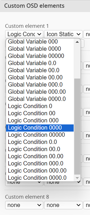
You may have noticed that there are plenty of different options for showing different formats of numbers. All numbers can be either positive or negative, which is why you will see an empty space to the left of a positive number. The whole numbers are pretty self-explanatory; just choose the appropriate number of digits for the number you are displaying. Numbers with decimal places need a little more explanation. In the programming framework, there are no floating point numbers, so there are no decimal spaces. How do we display a number with decimal places? We are simply faking it with math.
As an example, we want to show our distance to home in kilometres. The Flight - Home distance [m] operand in the programming framework returns metres, and we also want to show two decimal places. So how do we do it? Simply take the calculation we would normally need and shift it by the number of decimal places. For example, to convert our metres to kilometres we need to divide the metres by 1000, but if we want two decimal places, we shift the 1000 we use for the calculation right by 2. So instead of performing metres ÷ 1000, we perform metres ÷ 10.
To see that with real numbers, imagine that Flight - Home distance [m] is outputting 7243m. Remember that all results are whole numbers, with no floating point. So 7243 ÷ 10 = 724. Our custom OSD element display then takes that number and inserts the decimal place in the correct position, so our OSD will show 7.24km.
Simple Stall Warning Indicator
The logic checks if the Pitch is above 20°, the Virtual Airspeed has dropped below 35km/h, or the Throttle has been reduced below 48%, warning of a potential stall. Because most tip stall conditions are induced unknowingly by the pilot, this can help avoid such events.
Make sure you enable the Virtual Pitot if you do not use a real Pitot to better suit your aircraft. Pitch angle, airspeed, and throttle/delay values should be altered for best detection.
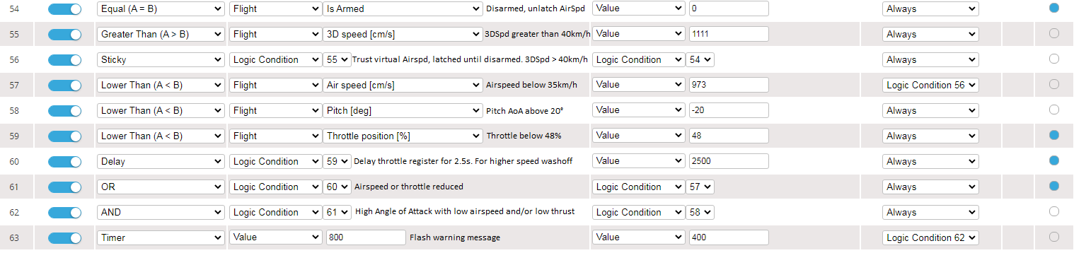
The message will display STALL WARNING with a warning symbol (221). The stall message will only appear when the conditions are met.

Please note that stalls are not caused directly by the speed of the aircraft. Stalls are caused by too little airflow over the wing, which is dependent on airspeed at the attitude of the aircraft.' Thus it may not detect all instances of a stall. Please do not be complacent. Aircraft with higher wing loading or poor stall characteristics should always be flown with caution when lowering the throttle to conserve energy.
Basic Switch Indicator
While there are switch indicators for the OSD, using Custom OSD elements can give you much more control over this. This is an example of how to set them up.
On the Programming Framework page, set up the Logic Conditions for the switch.

- LC0 takes the channel that you want to display the switch for, and subtracts 1000. This gives the switch a 0-1000 range.
- LC1 maps that range to 3 values: 0, 1, and 2.
- LC2 Adds the value from LC1 to the first switch indicator icon. 208 is switch down, 209 is switch in the middle, and 210 is switch up.
- LC3 sets GVAR 0 to the value from LC2. Note In INAV 8.0.0, you do not need LC3. You can use the output from LC2 directly to select the icon.
Then on the OSD page, add the Custom OSD element to handle the programming.

- Setup the icon. For INAV 7.1.x you will need to set this to Icon Global Variable and set the GV to the variable you chose in the programming. In this example, GV 0. With INAV 8.0.0 onwards, we don't need to use the Global Variable, so set this to use Icon from Logic Condition and set the LC to the appropriate Logic Condition, LC2 in our example.
- Next, we simply add the Text for what the switch represents.
If you want to swap the icon and text sides, simply switch the text and icon.
Please note that Custom element previews are added in INAV 8.0.0.
Currently, the Custom OSD icons in the OSD preview cannot retrieve the actual value from the global variable. The actual value of Global Variable 0 in the above example is 209, which displays the mid switch position:

Showing the altitude in different measurement units
In this example, we have our OSD set to metric, but some of the guys we fly with only understand feet, so we are going to be nice and have both measurement units on our OSD. We have the standard Altitude OSD element showing us the altitude in metres. Now we are going to add a second altitude custom element in feet. First, hop to the Programming page and we will perform the calculations.

In the first LC, we multiply the altitude in cm by 100. This allows us to divide with more accuracy. In the second LC, we divide the result of LC0 by 3048 to get the result in feet. Note that by multiplying by 100 and dividing by 3048, we are more accurate but will max out at 7045ft. Of course, we're not flying anywhere near that altitude; this calculation is just to show the limitations.
Next, head back to the OSD page and enable Custom Element 1. We will now make this show the altitude in feet.

In the first configuration space, we choose Logic Condition 0000 from the list. We will now choose LC1, which is the logic condition performing the divide. We can use 4 digits of precision because we know the number will not go over 7045. Next, we select Static Icon for the second configuration space. The character number is 120, so enter that. You can see that the OSD preview has updated and is showing a 4-digit number and the correct Alt Ft character.
What if we only wanted this altitude when we are under 400ft, for example? We can do this by adding one more line on the Programming page.

The third logic condition is only active if we are below 400 feet. So, back on the OSD page, we can change the visibility configuration to Logic Condition and LC2. This will only show our custom element when the altitude is below 400 ft.
